Search in MDM

Bulletin

Help with trooper isuzu synchronization 1993

  • Manual-Mecanica
  • Author of the subject
  • Offline
  • Fresh Boarder
  • Fresh Boarder
Further
14 years 11 months before #14898 by manual-mecanica
Help with Trooper Isuzu Synchronization 1993 Published by Manual-Mecanica
OLUPO PUT THE ENGINE 3.2L 6VD1 93 and I have not found how to place the marks. I appreciate that they provide me with the necessary information.

Please connect or create account to join the conversation.

  • Manual-Mecanica
  • Author of the subject
  • Offline
  • Fresh Boarder
  • Fresh Boarder
Further
14 years 11 months before #14905 by manual-mecanica
Disassembly:

Remove the air filter and hose.
Upper radiator crankcase.
Fan and viscous fan of the fan.
Fan pulley and drag straps.
Oil cooler tube.
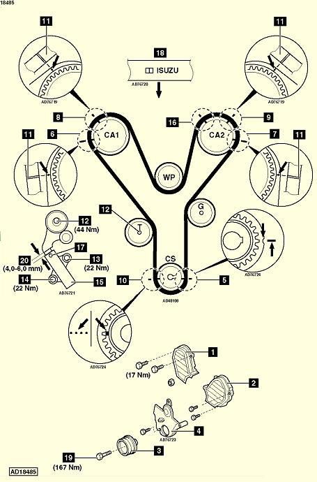
Right distribution lid (1)
Left distribution lid (2)
Crankshaft pulley (3)
Lower distribution cover (4)


Turn the crankshaft to the right until facing the adjustment mark (5).
Check the alignment of camshaft brands:
3.2 (6) engine (7)
3.5 motor (8) and (9)

Make sure the brands in the strap are aligned with the marks on the pinions (10) and (11)
Loosen the tensioning roller (12), turn the roller to the right away from the belt. Tighten the screw without blocking it.

Disassemble:

Automatic tensioner screws (13) and (14)
Automatic tensioner (15)
Distribution strap.

Please connect or create account to join the conversation.

  • Manual-Mecanica
  • Author of the subject
  • Offline
  • Fresh Boarder
  • Fresh Boarder
Further
14 years 11 months before #14907 by manual-mecanica
Assembly:

Check the alignment of the adjustment mark of the crankshaft pinion (5).
Check the alignment of the adjustment marks of the camshafts:

engine 3.5 (6) and (7)
engine 3.2 (8) and (9)

Note: Motor 3.5 An unequal ratio between the crazy axes of the dentated wheels and the camshaft can be the cause of an incorrect alignment of the camshaft if the strap has been broken. To proceed to the alignment of the camshaft Form:


turn the right camshaft pinion (CA1) to the right until the pinion is placed in position with the adjustment marks aligned (8) for this operation they can be necessary up to 9 laps.

Turn the left camshaft pinion (Ca2) to the right until the pinion is placed in its position (16) approximately at 10 of the clock. For this action they can be necessary until 9

90º Until the adjustment marks (9

)

. Align, then retain the pushing with a 1.4 mm diameter pin introduced by the hole of the tensioner body (

17

)

. Not

tense

.

​crankshaft, (3) tighten the screw (

19

)

by

hand

.

Tighten the crankshaft pulley screw (19) to 167 nm

.

Please connect or create account to join the conversation.

  • Manual-Mecanica
  • Author of the subject
  • Offline
  • Fresh Boarder
  • Fresh Boarder
Further
14 years 11 months before #14920 by manual-mecanica
Thanks for the information they send me, it served me to light the trooper. Thanks again for your help.

Please connect or create account to join the conversation.